

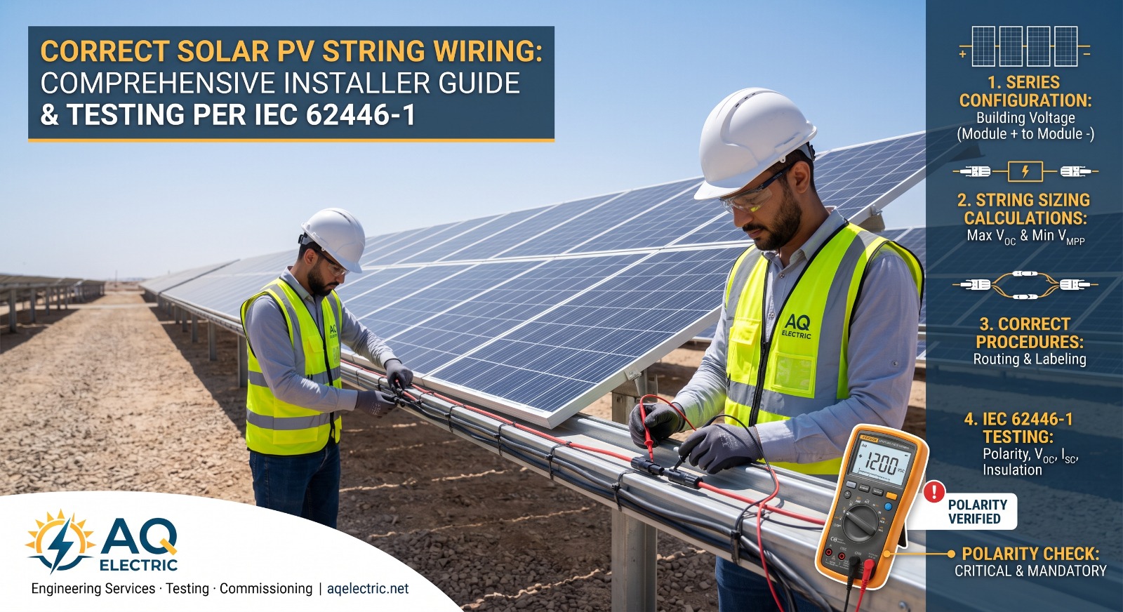
Solar string wiring is the DC-side foundation of every photovoltaic plant. Get it right and the rest of the system — inverters, monitoring, protection, MPPT tracking — performs as designed. Get it wrong, and you end up with reduced yield, tripped inverters, blown fuses, safety hazards, voided module warranties, and costly rework that could have been avoided in the first hour of installation.
This guide covers everything an installer, commissioning engineer, or project manager needs to understand about correct string wiring in a grid-connected solar PV system: how strings are configured, how they are sized, the correct wiring procedure, why polarity checks are non-negotiable, what cable and connector choices matter, and how to test the finished work against the IEC 62446-1 standard.
What Is a Solar PV String?
A solar PV string is a set of photovoltaic modules connected in series — the positive terminal of one module connected to the negative terminal of the next — so that their voltages add up while their currents remain the same. A single string is the fundamental building block of every grid-connected PV plant, from a small rooftop system to a multi-gigawatt utility installation.
Modules are wired in strings because inverters need a specific DC input voltage window to operate their Maximum Power Point Tracking (MPPT) algorithm effectively. A single module produces only 30–60 V; an inverter typically expects 400–1500 V. Stringing modules in series builds voltage up into the inverter’s operating range. Multiple strings are then wired in parallel — usually through a combiner box — to build the total current the inverter can handle.
The number of modules per string, the number of strings per combiner, and the number of combiners per inverter are all design decisions made during the electrical single-line diagram phase. When installers depart from that design — even with the right number of modules but in the wrong order or with reversed polarity somewhere — the entire chain of assumptions from module datasheet through to inverter selection is broken.
Series vs Parallel: How Strings Are Configured
Understanding the two connection modes and how they combine is the essential foundation for correct string wiring.
Series Connection (Building Voltage)
When modules are connected in series (positive to negative in sequence), the voltages add up while the current stays the same. Ten modules each producing 40 V at 10 A wired in series produce 400 V at 10 A at the end of the string. This is exactly what a solar string does.
Parallel Connection (Building Current)
When separate strings are wired in parallel (all positives together, all negatives together), the voltages stay the same while the currents add up. Five strings each producing 400 V at 10 A wired in parallel produce 400 V at 50 A total.
The Combined Array
A typical utility-scale array combines both: modules in series make up strings, and strings in parallel make up arrays that feed each inverter input. Combiner boxes centralise the parallel connections, provide string-level fusing, and often include monitoring shunts that measure the current of each string independently.
Why this matters at wiring time
Because voltages add in series, a reversed polarity on even one module in a 20-module string subtracts that module’s voltage instead of adding it. Instead of 800 V, you get 720 V — and the missing 80 V will either trip protection or fall outside the inverter’s MPPT window entirely.
String Sizing Fundamentals
Before a single cable is pulled, the designer calculates how many modules should be in each string. The math is driven by three constraints from the inverter datasheet and one from the module datasheet, plus the extreme temperatures the site will see.
Maximum String Voltage (Cold-Temperature VOC)
The open-circuit voltage (VOC) of a module rises as temperature falls. In a cold morning startup, string voltage can be 15–20% higher than the datasheet value at Standard Test Conditions (STC). The design must ensure that VOC at the site’s lowest expected temperature never exceeds the inverter’s absolute maximum input voltage — commonly 1000 V, 1100 V, or 1500 V depending on the equipment.
Minimum String Voltage (Hot-Temperature VMP)
Conversely, VMP (voltage at maximum power) falls as temperature rises. On the hottest day, string voltage must remain above the inverter’s minimum MPPT window; otherwise the inverter drops out of tracking and yield collapses.
Maximum String Current (ISC)
Each string’s short-circuit current (ISC) plus a safety margin must remain within the string-fuse rating and within the inverter’s per-input current limit. This constrains parallel connections more than series ones, but it directly affects combiner design.
A Worked Example
A common utility module today has VOC = 51 V, VMP = 42 V, and ISC = 13.5 A at STC. A 1500 V inverter with an MPPT range of 875–1300 V and a coldest expected cell temperature of −5 °C at the site produces a maximum string length of roughly 27 modules and a minimum of about 22 modules. The designer picks 24–26 depending on the specific climate profile. Deviating from this at wiring time is not something the installer can decide informally.
AQ Electric provides IV curve tracing, string testing, and full IEC 62446 commissioning — call +962 79 51 54 126.
The Correct String Wiring Procedure
Every string wiring job on a solar PV site should follow the same disciplined procedure. Cutting corners here creates faults that only surface at commissioning — by which time correcting them is 10× more expensive.
Step 1: Verify the Design Drawing on Site
Before touching a single cable, confirm the design drawing matches the physical array: the correct number of modules per string, the correct string routing, and the correct combiner box assignment. Design changes made in the field without engineering approval are the most common source of downstream problems.
Step 2: Identify Positive and Negative Terminals on Every Module
Modules leave the factory clearly marked: positive (usually longer cable or a “+” symbol on the junction box) and negative. Do not assume — confirm by module manufacturer’s marking on every batch, because factory changes and shipping errors do happen.
Step 3: Connect Positive to Negative in Sequence
Working from the start of the string, connect the positive of module 1 to the negative of module 2, the positive of module 2 to the negative of module 3, and so on. The unconnected negative of the first module and the unconnected positive of the last module are the two string ends that feed the combiner box.
Step 4: Route Cables Safely
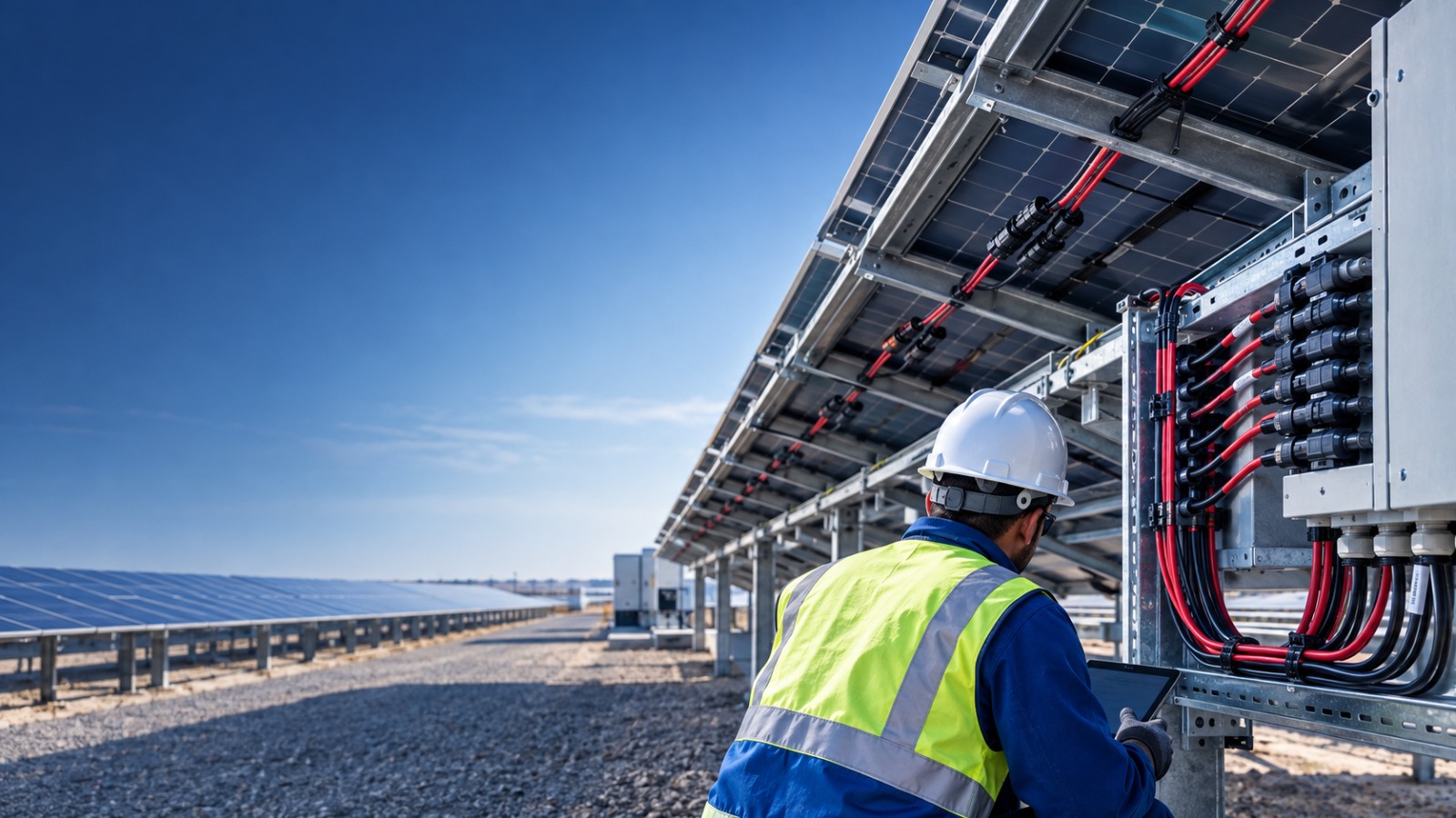
DC string cables should be secured to the module structure with UV-resistant cable ties or clips, avoiding sharp edges, avoiding traps for water, and maintaining a minimum bend radius per the cable specification. Cables should never be left dangling under panels where wind or wildlife can damage them.
Step 5: Label Both Ends of Every String
Each string end should be labelled with the string ID (e.g., “CB01-S07”) at both the module end and the combiner end. Unlabelled strings are the single largest cause of confusion during fault-finding and O&M work over the plant’s 25-year life.
Step 6: Perform Polarity and Voltage Checks Before Energising
Before connecting the string to the combiner, verify polarity and measure the open-circuit voltage at the string end. Both values should match the design expectation within a reasonable tolerance for the current irradiance and temperature.
Solar Panel Polarity: The Critical Check
Solar panel polarity is the direction of DC current flow — positive to negative — through each module and through the completed string. Correct polarity is the difference between a plant that starts producing on day one and a plant that trips protection, damages inverters, or worse.
Why Polarity Matters
Modern string inverters have internal reverse-polarity protection, but that protection is a last line of defence, not a substitute for correct wiring. A reversed string on connection can:
- Trigger inverter fault codes and prevent the input from operating at all
- Blow the string fuse in the combiner box (best case)
- Damage inverter input capacitors or MPPT circuitry (worst case)
- Create an unexpected arc during connection under sunlight, presenting a fire risk
- Void the inverter warranty if damage is traced to installer error
How to Check Solar Panel Polarity Correctly
Polarity is verified with a properly-rated DC multimeter or a dedicated PV tester. The procedure is:
- Place the string in daylight so it is producing voltage.
- Set the multimeter to DC voltage on a range that covers the expected string VOC.
- Touch the red probe to the positive string end and the black probe to the negative string end.
- A positive reading confirms correct polarity. A negative reading (or a “−” sign on the display) indicates reversed polarity somewhere in the string.
If polarity is reversed, isolate the string and trace back module by module until the reversed connection is found. Do not attempt to fix a live reversed string by disconnecting it under load — isolate the array-side first if possible, or wait for low-light conditions.
The IEC 62446-1 polarity requirement
Polarity verification is a Category 1 mandatory test under IEC 62446-1 and must be documented for every string in the commissioning test report. Skipping it is a compliance failure, not just an installation oversight. See our complete IEC 62446-1 guide for the full test procedure.
Cable Selection and Sizing
String cables spend 25 years exposed to UV radiation, extreme temperature swings, moisture, sand abrasion, and mechanical stress from wind loading. Only cables specifically manufactured for PV DC service should be used. In the MENA region — where UV intensity and surface temperatures exceed most global norms — cable selection is especially critical.
The PV DC Cable Standard
Solar DC cables should meet EN 50618 (European standard for PV DC cables) or equivalent. These cables are double-insulated, halogen-free, UV-stable, and rated for continuous operation at 90 °C or 120 °C depending on the specification. Generic building wire — even where it appears to fit — is not acceptable for exposed DC runs.
Cross-Section Sizing
Cable cross-section is sized to two constraints: current-carrying capacity (ampacity) and voltage drop over the cable run. Common sizes are 4 mm² and 6 mm² for string cables. Voltage drop from the array to the combiner should typically be kept under 1% at full load, and total DC voltage drop from array to inverter under 2%.
Connectors and Proper Termination
Solar-specific connectors — most commonly the MC4 standard — are what allow strings to be assembled quickly on site. But connector failure is one of the most common long-term fault modes in PV plants, and almost every connector failure traces back to installation practice.
- Always use matched connectors. An MC4 male mated to a compatible-but-not-identical MC4 clone is one of the leading causes of connector heating and eventual failure. Both halves should be from the same manufacturer.
- Use the correct crimping tool. Hand-squeezing a crimp with pliers produces a joint that looks fine on day one and burns out three years later. The manufacturer’s specified crimp tool is not optional.
- Match cable cross-section to connector. A 6 mm² cable crimped into a 4 mm²-rated connector creates a mechanical mismatch that also causes long-term heating.
- Never re-terminate a used connector. Once crimped, the connector body is permanently deformed. Field re-termination requires a new connector.
String Combiners and Fuses
String combiner boxes bring multiple strings together into a single DC output that feeds the inverter. Each string enters through its own fused input, and modern “smart” combiners include per-string current monitoring, temperature sensing, and remote fault reporting via the plant SCADA system.
String Fuses
Every string entering the combiner is protected by a dedicated fuse sized to protect the string cable against fault currents flowing back from other parallel strings. Common ratings are 15 A or 20 A depending on module current and string count. Fuses that repeatedly blow indicate a real fault — not a fuse that should simply be replaced with a bigger one.
Combiner Enclosure Environment
Combiners sit in direct sun and are subject to daily thermal cycling. Enclosure IP rating (IP65 minimum for outdoor use), internal temperature management, and gland-plate cable entry quality all directly affect the reliability of the DC array over its life.
Common String Wiring Mistakes
From more than a decade of commissioning and inspecting solar PV plants across Jordan, Egypt, Saudi Arabia, and the wider MENA region, six string wiring mistakes appear again and again in field audits.
1. Reversed Polarity Somewhere in the String
A single module wired backwards subtracts its voltage from the string total, creating a mismatched string that either won’t start the inverter or produces well below the expected yield.
2. Mismatched String Lengths in Parallel
Two parallel strings with different module counts have different VMP values, forcing current to circulate between them and reducing the yield of both. Every parallel-combined string must have identical module count.
3. Non-Matched Connector Brands
An MC4 from manufacturer A mated with an MC4-compatible connector from manufacturer B may fit but creates a poor electrical contact. Field failures traceable to this issue can take years to manifest but are almost impossible to fully diagnose without disassembling the entire array.
4. Undersized DC Cable
Using 4 mm² where the design specifies 6 mm² because 4 mm² was on the truck is a chronic problem. The result is excessive voltage drop, heating, and often nuisance-tripping on hot days when the plant should be at peak output.
5. Missing or Illegible Labelling
Strings and cables that are not labelled become a nightmare for the first O&M team to face a fault. Twenty minutes of labelling at installation saves days of investigation later.
6. Skipping the Pre-Energisation Polarity Check
Every string end must have its polarity and VOC verified before it is connected to the combiner. Skipping this “because we’re running late” is how reversed polarity reaches the inverter.
Testing String Wiring per IEC 62446-1
Every string wiring job should be closed out with a formal test regime that follows the international standard IEC 62446-1. The Category 1 tests that apply to every string are:
- Visual inspection — cable routing, connector condition, labelling.
- Continuity test — verification of protective earthing continuity across module frames and structure.
- Polarity check — DC voltmeter test at the string end, documented per string.
- Open-circuit voltage (VOC) measurement — compared against the expected value calculated from module datasheet and current temperature.
- Short-circuit current (ISC) or operating current measurement — compared against expected value at current irradiance.
- Insulation resistance test — verification that the DC circuit is properly isolated from earth.
For larger commercial and utility-scale plants, IEC 62446-1 Category 2 adds string I-V curve measurement and infrared thermographic inspection to the above. The complete test procedures, expected pass criteria, and documentation format are all specified in the standard — and the resulting test report is what the plant owner, lender, and O&M team will refer to for the plant’s entire life.
Safety Considerations on Live Strings
Solar strings produce DC voltage whenever there is light on the modules. Unlike an AC system, there is no simple “switch off” — the array itself is the energy source, and it cannot be de-energised except by covering the modules or waiting for darkness.
Working practices should therefore always assume DC voltage is present:
- Use insulated tools rated for the string VOC.
- Wear insulated gloves rated for DC service.
- Never disconnect a live string under load — DC arcs do not self-extinguish and can cause severe burns and fires.
- Follow a documented lockout-tagout procedure at the combiner box and inverter DC isolator before opening any string.
- Use module covers or coverings for any work that requires strings to be de-energised.
Related AQ Electric Services
Explore our full portfolio — each service on its own page.
⚡Testing & Commissioning🔧Operation & Maintenance🔍Third-Party Inspection✓Quality Assurance (FAT & SAT)📐Engineering Services🚁Drone Inspection🎓Training Services✉Speak to an Engineer
Need Solar String Testing on Your PV Plant?
AQ Electric provides string testing, IV curve tracing, polarity verification, and full IEC 62446-1 commissioning across Jordan, Egypt, Saudi Arabia, the UAE, Oman, Kuwait, and Qatar.
Frequently Asked Questions
What is a solar PV string in simple terms?
A string is a set of PV modules connected in series (positive to negative in sequence) so their voltages add up to reach the input voltage the inverter needs to operate.
How do I check solar panel polarity?
Use a DC multimeter set to a voltage range covering the expected string VOC. Red probe on positive, black probe on negative. A positive reading confirms correct polarity; a negative reading means somewhere in the string a connection is reversed.
What causes reverse polarity in solar strings?
Almost always installer error — connecting a module the wrong way round, mislabelled cables, or confusing positive and negative on the combiner side. Factory mis-marking of modules also happens occasionally.
How many solar panels can be in one string?
It depends on the module VOC, the site’s minimum expected temperature, and the inverter’s maximum input voltage. A typical 1500 V inverter with modern high-power modules allows 22–28 modules per string.
Do string wiring mistakes void the module warranty?
Yes — most module manufacturers explicitly exclude damage caused by incorrect wiring, incorrect connectors, or system voltage exceeding the module’s maximum rating. This is one reason IEC 62446 commissioning records matter for warranty claims.
What is the IEC 62446-1 string test procedure?
At minimum: visual inspection, earthing continuity, polarity check, VOC measurement against expected value, ISC or operating current measurement, and insulation resistance test. See our full IEC 62446-1 guide for the detailed procedure.
Bankable String Testing and Commissioning — Delivered Across MENA
AQ Electric provides ISO-certified solar PV testing, commissioning, and inspection services with over 1.0 GW of PV project experience. Trusted by ACWA Power, NOMAC, Wärtsilä, SEPCO, Belectric, and Philadelphia Solar.
PV projects supported
MENA countries covered
ISO certifications9001 · 14001 · 45001
Founded in Jordan