

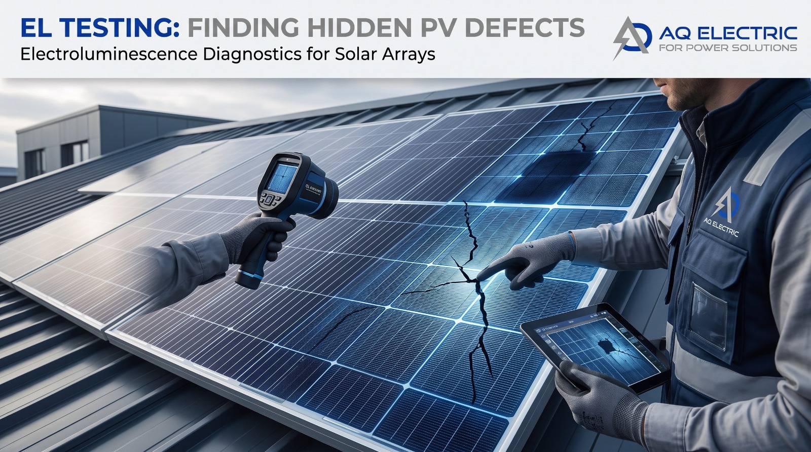
AQ Electric uses electroluminescence testing on solar PV projects across the MENA region because it reveals what no other test can: the microscopic cracks, cell defects, and hidden damage that silently erode a module’s output long before they become visible. With more than 1.0 GW of PV project experience, AQ Electric’s engineering team has learned that the most expensive module failures almost always begin as defects invisible to the naked eye — and that electroluminescence testing is the only field technique that catches them early enough to matter. When a warranty claim, a bankability question, or an unexplained yield loss hinges on the true condition of the modules, electroluminescence testing is how the answer is found.
This article explains electroluminescence testing for solar PV from the ground up: what the technique is and the physics behind it, what defects it detects, how EL testing is performed on-site, how it compares with IV curve tracing and thermography, the international standards that now govern it, and why it has become essential across commissioning, warranty disputes, and ongoing operation and maintenance. Whether you are an EPC closing out a project, an owner protecting a warranty claim, or a lender’s advisor assessing module quality, this is the practical reference on the most revealing module-level diagnostic in solar — and how AQ Electric puts it to work.
What Is Electroluminescence Testing?
Electroluminescence testing — commonly abbreviated EL testing — is a non-destructive diagnostic technique that reveals internal defects in solar PV modules by capturing the near-infrared light the modules emit when an electric current is passed through them in darkness. It is, in effect, an X-ray for solar panels: it makes visible the cracks, breaks, and cell-level faults that are completely invisible to the naked eye and undetectable by most other field tests.
The power of electroluminescence testing lies in its ability to see inside the module. A visual inspection catches broken glass and obvious damage. IV curve tracing detects electrical underperformance. Thermography finds hot spots. But microcracks — the tiny fractures in silicon cells that are the leading precursor to long-term module failure — are often silent to all of these until they have already caused damage. Electroluminescence testing catches them at their earliest stage, which is exactly why it has become an indispensable part of the modern solar testing toolkit and a core service in AQ Electric’s diagnostics offering.
The Physics: Why Modules Glow
Electroluminescence testing works by exploiting a property of silicon solar cells: when a forward bias current is applied to a cell in darkness, it emits light — the reverse of the normal photovoltaic process. Instead of converting light into electricity, the energised cell converts electricity into light. Because the band gap of silicon is approximately 1.12 eV, the light emitted peaks at a wavelength of around 1,150 nanometres, in the near-infrared spectrum that is invisible to the human eye but readily captured by a specialised camera.
The intensity of the emitted light corresponds directly to the local electrical activity in the cell. Areas that are functioning normally glow brightly and uniformly; areas with defects — cracks, broken contacts, disconnected regions — appear as dark zones because current cannot flow through them to produce light. This is the essence of electroluminescence testing: the resulting grayscale image maps the electrical health of every cell in the module, with defects appearing as dark lines, spots, or regions against the bright active area. An experienced analyst reads these patterns to identify not just that a defect exists, but what type it is and how it will affect performance.
Why darkness and night testing
Because the emitted light is faint and in the near-infrared range, electroluminescence testing must be conducted in darkness — which is why on-site EL testing is performed at night. This has a practical advantage: testing at night means plant production is not interrupted during daylight generation hours.
What EL Testing Detects
Electroluminescence testing detects a comprehensive range of module defects, many of which are invisible to every other field technique. The most important include:
- Microcracks — tiny fractures in the silicon cells, invisible to the naked eye, caused by manufacturing stress, transport, handling, installation, or environmental loads such as hail and wind. Microcracks are the single most important defect EL testing catches, because they are the leading precursor to long-term failure.
- Cell cracks and breaks — larger fractures that appear as thin dark lines (cracks) or dark polygonal regions (breaks) where sections of cell are electrically isolated.
- Broken or inactive cells — cells or regions no longer contributing to power generation, appearing as dark areas.
- Finger interruptions — breaks in the screen-printed grid lines that collect current, causing localised performance loss.
- Potential-Induced Degradation (PID) — a degradation mechanism that EL testing can reveal through characteristic darkening patterns.
- Soldering defects and poor contacts — regions of poor electrical connection that show as dimmer areas.
- Cell mixing and process defects — cells with differing electrical performance introduced during manufacturing.
- Hidden cracks along grid lines or cell edges — linear and cross-pattern cracks that impair cell function.
Critically, cracks detected by electroluminescence testing can, over time, lead to hot spots, increase the probability of PID, and drive high rates of degradation — a loss of active cell area that reduces the output of the entire string containing the defective module. Catching them early through EL testing is what prevents a minor manufacturing flaw from becoming a plant-wide yield problem.
How On-Site EL Testing Works
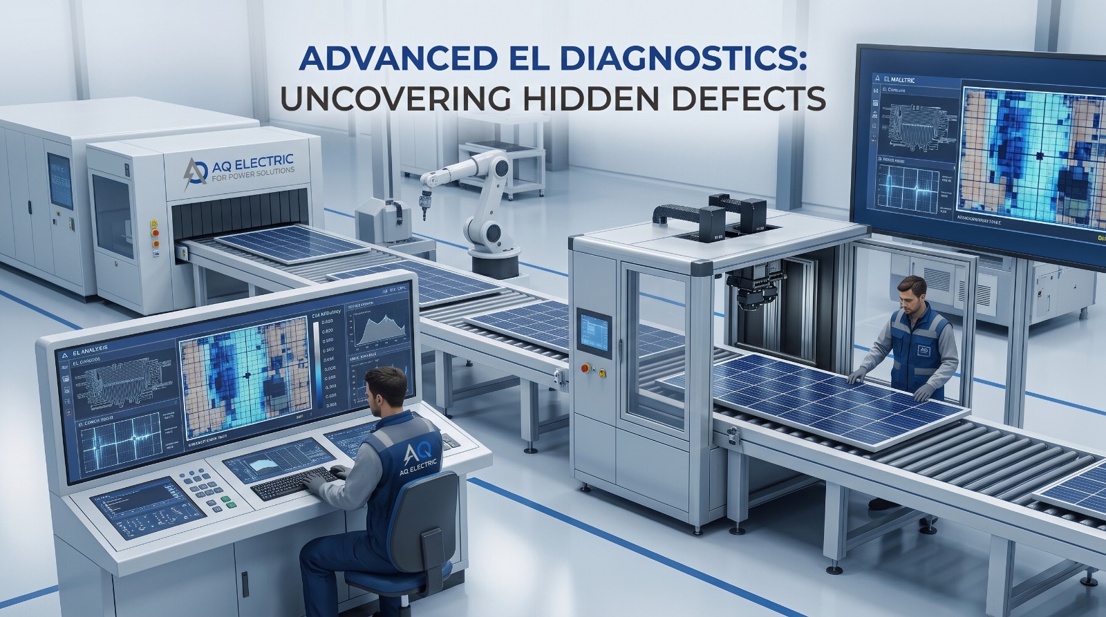
While electroluminescence testing was originally a laboratory technique, modern equipment allows it to be performed on-site at operating solar plants — the approach AQ Electric delivers. On-site EL testing follows a disciplined procedure:
Step 1: Night-Time Setup
Because EL testing requires darkness, the campaign is conducted at night. The team sets up after sunset, when the faint near-infrared emission can be captured without interference from ambient light.
Step 2: Energise the Modules
A DC power supply applies a forward bias current to the module or string under test, typically at or slightly above the rated voltage, injecting the current that induces electroluminescence. This is the “source” that makes the cells emit light.
Step 3: Capture the Images
A specialised camera with near-infrared sensitivity captures the electroluminescence image of each module. The result is a high-resolution grayscale image in which defects appear as dark features against the bright active cell area. On a utility-scale plant, thousands of images may be captured across a testing campaign.
Step 4: Analyse and Report
Each image is analysed — increasingly with the support of automated defect-recognition tools, but always with expert oversight — to classify the defects found, assess their severity, and estimate their impact on module performance. AQ Electric’s electroluminescence testing closes with a detailed report documenting every defective module, its location, the defect type, and the recommended action — the documentation needed for warranty claims, insurance, or O&M planning.
AQ Electric delivers on-site EL testing across MENA — call +962 79 51 54 126.
EL Testing vs IV Curve Tracing vs Thermography
Electroluminescence testing is one of three complementary DC-side diagnostics, and understanding how they differ clarifies when each is used. The strongest testing programmes use all three together.
| Technique | What it detects | When performed | Best at |
|---|---|---|---|
| Electroluminescence (EL) | Microcracks, cell defects, PID, breaks | Night (darkness required) | Internal, invisible module defects |
| IV curve tracing | Electrical underperformance, mismatch, resistance | Day (needs irradiance) | Quantifying string electrical health |
| Thermography (IR) | Hot spots, thermal anomalies, connection faults | Day (under load) | Locating active faults across large areas |
The key distinction is that electroluminescence testing detects defects before they become electrically or thermally significant. A microcrack may not yet affect the IV curve or produce a hot spot — but EL testing sees it, allowing intervention before it develops into measurable loss. This is why EL testing is the definitive tool for module-level quality assessment, working alongside AQ Electric’s IV curve tracing services and drone thermographic inspection to form a complete diagnostic picture.
The Standards Governing EL Testing
Electroluminescence testing has moved from an ad-hoc technique to a standardised discipline, and a credible EL testing provider works to the recognised international standards. The most important are:
- IEC TS 62446-4 — the technical specification for outdoor electroluminescence imaging of photovoltaic modules and plants, whose standardisation is a recent development as of 2025. This is the key emerging standard specifically governing on-site EL testing.
- IEC TS 60904-13 — the standard covering electroluminescence of photovoltaic devices, defining the measurement technique.
- VDE SPEC 90031 — a specification providing terms and classification for electroluminescence of PV modules, used for consistent defect nomenclature.
EL testing also sits within the broader IEC 62446 family that governs PV commissioning and testing. Under IEC 62446-1, advanced diagnostics such as electroluminescence imaging fall within Category 3 testing — the level expected on high-value and bankable projects. For a complete walkthrough of that framework, see AQ Electric’s IEC 62446-1 article. EU-funded SolarBankability studies and SolarPower Europe both identify on-site EL imaging, alongside IEC 62446 testing, as a best practice for bankable projects.
When EL Testing Matters Most
Electroluminescence testing delivers value at several distinct points in a solar plant’s life:
At Commissioning
EL testing at commissioning establishes a baseline record of module condition before the plant enters operation — documenting any factory or transport damage while responsibility can still be assigned. This baseline is invaluable for future warranty claims, since microcracks that appear later can be compared against the commissioning record.
After Transport and Installation
Because microcracks frequently occur during shipping, handling, and installation, electroluminescence testing after these stages catches damage introduced on the way to and onto the site — the difference between a successful manufacturer or workmanship warranty claim and absorbing the cost yourself.
During Operation
Periodic EL testing during operation tracks the development of defects over time, identifying modules whose degradation is accelerating and informing replacement decisions before they drag down entire strings.
After Extreme Weather
Following hail, storms, or extreme wind events, electroluminescence testing assesses whether modules have suffered internal damage — essential for insurance claims after weather events.
EL Testing and Warranty Claims
One of the most commercially important applications of electroluminescence testing is in warranty and insurance disputes. Module warranties typically exclude damage caused by improper handling or installation — so when microcracks appear, the critical question is when and how they occurred. Electroluminescence testing provides the investor- and insurance-grade evidence needed to answer that question.
By capturing high-resolution EL images and comparing them against baseline records, electroluminescence testing can help establish whether a defect originated in manufacturing (a manufacturer warranty claim), during transport or installation (a workmanship or shipping claim), or from an operational event such as a storm (an insurance claim). Without this evidence, an owner facing widespread microcracks may have no recourse and may have to absorb the full replacement cost. This is why sophisticated owners and lenders increasingly require electroluminescence testing as standard practice — it converts an unprovable suspicion into a documented, defensible claim. AQ Electric’s EL testing reports are structured precisely to serve this evidentiary purpose.
EL Testing in MENA Conditions
Performing electroluminescence testing in the MENA region introduces specific considerations that AQ Electric’s field experience across Jordan, Egypt, and Saudi Arabia has refined into standard practice.
Night-Time Temperature Advantage
Because EL testing is performed at night, it sidesteps the extreme daytime heat of the MENA region — but the team must still manage significant residual heat and plan campaigns around the coolest, most stable night-time conditions for both equipment performance and worker safety.
Dust on the Module Surface
Heavy MENA soiling can obscure the module surface, so electroluminescence testing may require surface cleaning beforehand to capture clear images. Coordinating EL testing with the cleaning schedule is part of efficient campaign planning.
Scale and Sampling Strategy
On the vast utility-scale plants typical of the region, testing every module is often impractical, so a statistically robust sampling strategy — or full testing of suspect strings identified by IV curve tracing — is designed to balance thoroughness against cost. This is where combining EL testing with other diagnostics pays off: IV curve tracing and thermography identify suspect areas, and electroluminescence testing then confirms the module-level cause.
AQ Electric’s EL Testing Services
AQ Electric for Power Solutions, founded in Jordan in 2019 and expanded to Egypt in 2021, provides specialist electroluminescence testing across the MENA region as part of its complete solar PV testing and diagnostics offering. With over 1.0 GW of PV project experience and an ISO 9001, ISO 14001, and ISO 45001-certified management system, AQ Electric delivers on-site EL testing to the emerging IEC TS 62446-4 standard, integrated with its broader testing capabilities.
Our engineering team has delivered advanced diagnostics across a range of regional projects, working with clients including ACWA Power, NOMAC, SEPCO, Power China, CEEC, and Philadelphia Solar. Because AQ Electric delivers electroluminescence testing alongside IV curve tracing, thermographic drone inspection, and full commissioning in-house, we can combine techniques intelligently — using each to confirm and complement the others — rather than treating EL testing as an isolated service.
Our electroluminescence testing services include night-time on-site imaging, module energisation, high-resolution near-infrared capture, expert defect classification, and a detailed report documenting every defective module and its recommended action. Whether you need commissioning-stage EL testing to establish a baseline, warranty-dispute EL testing to build a claim, or periodic operational EL testing to protect long-term yield, AQ Electric’s team has the equipment, the standards, and the regional expertise to deliver it. Explore our dedicated EL testing services or read how it fits into the operational phase in our solar O&M article.
AQ Electric Solar Testing & Diagnostics
The full diagnostic scope, delivered in-house across the MENA region.
🔬EL Testing📊IV Curve Tracing🚁Drone Inspection⚡Testing & Commissioning🔧Operation & Maintenance🔍Third-Party Inspection✓Quality Assurance (FAT & SAT)✉Speak to an Engineer
Frequently Asked Questions
What is electroluminescence testing in solar PV?
Electroluminescence testing is a non-destructive technique that reveals internal module defects by capturing the near-infrared light modules emit when a current is passed through them in darkness. It detects microcracks, cell breaks, PID, and other faults invisible to the naked eye and to most other tests.
Why is EL testing done at night?
The light emitted by energised cells is faint and in the near-infrared range, so it must be captured in darkness. On-site EL testing is therefore performed at night — which conveniently means plant production is not interrupted during daylight generation hours.
What defects can electroluminescence testing detect?
Microcracks, cell cracks and breaks, broken or inactive cells, finger interruptions, potential-induced degradation (PID), soldering defects, and process faults — many of which are invisible to visual inspection, IV curve tracing, and thermography until they have already caused damage.
How is EL testing different from IV curve tracing and thermography?
EL testing detects internal module defects before they become electrically or thermally significant. IV curve tracing measures electrical underperformance, and thermography finds hot spots. The strongest programmes use all three together — EL testing confirms the module-level cause of issues the others flag.
Which standards govern electroluminescence testing?
IEC TS 62446-4 (outdoor EL imaging, standardised as of 2025), IEC TS 60904-13 (EL of PV devices), and VDE SPEC 90031 (terms and classification). EL imaging is also a Category 3 diagnostic under IEC 62446-1 for high-value projects.
Why does EL testing matter for warranty claims?
EL testing provides investor- and insurance-grade evidence of when and how microcracks occurred — distinguishing manufacturing defects, transport or installation damage, and weather events. This evidence is often the difference between a successful warranty claim and absorbing the replacement cost.
Does AQ Electric provide EL testing across the MENA region?
Yes. AQ Electric provides on-site electroluminescence testing across Jordan, Egypt, Saudi Arabia, and the wider MENA region, integrated with IV curve tracing, thermography, and commissioning, with over 1.0 GW of project experience.
See the Defects Hiding Inside Your Modules
Electroluminescence testing reveals the microcracks and hidden faults that every other test misses — and AQ Electric delivers it on-site across the MENA region, integrated with IV curve tracing and thermography. Over 1.0 GW of project experience, ISO-certified, and trusted by ACWA Power, NOMAC, SEPCO, CEEC, and Philadelphia Solar.
PV projects supported
MENA countries covered
ISO certifications9001 · 14001 · 45001
Founded in Jordan