

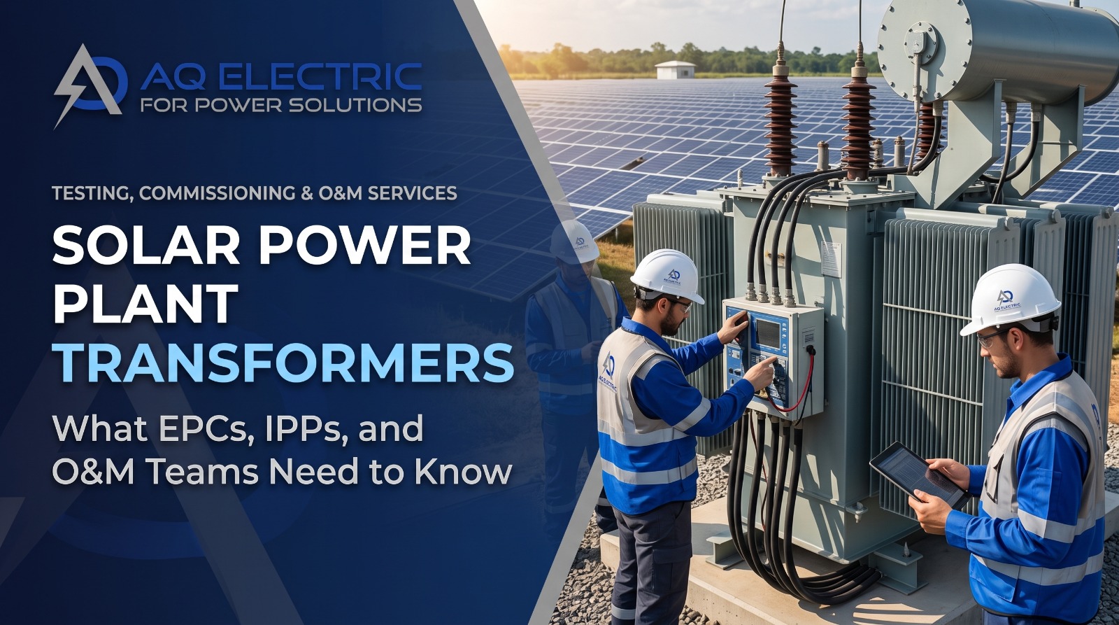
Every grid-connected solar photovoltaic plant on the planet depends on transformers — and yet transformers are, alongside inverters, one of the most misunderstood pieces of equipment in the entire solar value chain. When they work, no one notices. When they fail, they take megawatt-hours of production offline for weeks and generate repair costs that dwarf almost any other single failure mode in a PV plant.
A transformer in a solar power plant is not a passive component that can be selected on price and forgotten. Solar plants impose duty cycles on transformers that no traditional power-system application ever produced — daily thermal cycling from cold-morning start to hot-afternoon full load, harmonic content from inverters, unpredictable partial-load operation, and in the MENA region a punishing ambient temperature envelope. This guide is written for EPC contractors specifying transformers, IPP owners underwriting them, and O&M teams keeping them in service across their 25-to-30 year design life.
What Solar Power Plant Transformers Actually Do
A solar transformer’s core job is voltage transformation: matching the voltage of the electricity that leaves the inverters to the voltage the grid requires. Modules produce DC. Inverters convert that DC into low-voltage AC (typically 400 V to 800 V for utility-scale central inverters, or a mix of AC voltages for distributed string inverters). Grid connection almost always happens at medium voltage (11 kV, 22 kV, 33 kV) or high voltage (66 kV, 132 kV, 220 kV) — and something has to bridge that gap.
That something is one or several transformers, arranged in a hierarchy that walks the voltage up from inverter output to the point of grid connection. Alongside voltage transformation, transformers also provide galvanic isolation between the inverter side and the grid, adapt to grounding schemes, and often serve as the point at which protective relaying and metering interface with the plant.
Because every joule of energy the plant produces passes through at least one transformer — and often two or three in sequence — transformer availability directly caps plant availability. A plant with 99.5% inverter availability and 98% transformer availability has 97.5% combined availability, not 99.5%.
The Three Types of Transformer in a Solar Plant
A modern utility-scale solar plant typically contains three distinct types of transformer, each with a specific role and its own selection, testing, and maintenance requirements.
1. Inverter Transformer (LV to MV)
The inverter transformer takes the low-voltage AC output from a central inverter (or a bank of string inverters) and steps it up to the plant’s medium-voltage collection network — typically 22 kV or 33 kV. On large plants, these transformers are commonly configured with two or more low-voltage windings, allowing a single transformer to serve two inverter blocks and reduce the total transformer count.
Ratings typically range from 1.6 MVA to 5 MVA per unit, and the transformer is usually oil-immersed for the loss profile and cooling capacity that solar duty demands. These are the workhorses of the plant — the largest population of transformers on site, and typically the most exposed to the daily cyclic stress of PV operation.
2. Main / Step-Up Transformer (MV to HV)
The main transformer sits at the plant substation and steps the collected medium voltage up to the transmission voltage at which the plant connects to the grid — 132 kV is common in MENA utility-scale plants, with 66 kV and 220 kV also used depending on the local grid code. This is typically a single very large transformer (or two operating in parallel for redundancy) rated at the plant’s full nameplate capacity.
Because loss of the main transformer takes the entire plant offline, its specification, testing, and O&M receive disproportionate scrutiny. On-load tap changers (OLTC), differential protection, gas-actuated Buchholz relays, and dissolved gas analysis (DGA) monitoring are typically all part of the main transformer package.
3. Auxiliary Transformer (Station Service)
An auxiliary transformer in a solar power plant provides the internal station-service power that the plant needs to operate itself: SCADA and monitoring systems, security lighting, air-conditioning for control rooms, motorised valves and dampers, battery chargers for protection systems, and the cooling equipment on the main transformer itself.
Auxiliary transformers are much smaller than the power transformers — typically 25 kVA to 500 kVA — but they are safety-critical. A failed auxiliary transformer can trigger a full plant shutdown even when every megawatt of PV generation is intact, simply because the SCADA system can no longer communicate with the grid operator or the protection system loses supply.
A common oversight
Auxiliary transformers are often specified after the main transformers are already ordered, treated as an afterthought, and installed with less redundancy. In practice, they are one of the most common single points of failure that take an otherwise-healthy solar plant offline.
Design Considerations Specific to Solar
Traditional power-system transformer specifications assume relatively steady loading, moderate ambient temperatures, and sinusoidal current. Solar plants violate all three assumptions, and any transformer specified without these considerations will underperform its expected life.
Cyclic Duty and Thermal Aging
A solar plant transformer goes from near-zero load overnight to near-full load at midday, every day, for 25 years. Each cycle causes thermal expansion and contraction of winding insulation, oil, and mechanical support structures. Selecting a transformer specifically rated for cyclic PV duty (per IEC standards for PV-specific applications) is not optional at utility scale.
Harmonic Content
Modern inverters produce output current with low but non-zero harmonic distortion. K-factor derating (or K-rated transformer selection) accounts for the additional heating that harmonic currents produce in the transformer windings. Ignoring this leads to hot-spot temperatures that shorten insulation life.
Temperature Rise Under MENA Ambient
IEC standards specify transformer temperature rise limits above a reference ambient (typically 40 °C). In the Gulf, summer ambient regularly exceeds 45 °C, and the transformer enclosure sits in full sun. Transformers must be selected with derating that reflects the actual site ambient, not the reference value on the datasheet.
Insulation and Oil Selection
Traditional mineral oil is being displaced by natural ester and synthetic ester fluids on utility-scale solar plants because of their higher flash point (fire safety), superior insulation life at high temperature, and biodegradability. The lifecycle cost gap has narrowed to the point where esters often win on economics as well as safety.
AQ Electric’s engineering team delivers FAT, SAT, and commissioning testing across MENA — call +962 79 51 54 126.
Transformer Testing at FAT and SAT
Every power transformer in a solar plant is subjected to two rounds of formal factory and site testing before it ever carries load: Factory Acceptance Testing (FAT) at the manufacturer’s works and Site Acceptance Testing (SAT) after installation. Both are governed by IEC 60076 and are non-negotiable for bankable projects.
Factory Acceptance Tests (Selected)
- Winding resistance at all tap positions — baseline for future comparison.
- Voltage ratio and polarity at all taps.
- Magnetic balance to detect winding faults.
- Insulation resistance and polarisation index.
- No-load losses and current at rated voltage.
- Load losses and impedance at rated current.
- Temperature-rise test under full load until thermal stabilisation.
- Lightning impulse and switching impulse tests for insulation coordination.
- Partial discharge measurement to detect insulation weaknesses.
- Applied voltage and induced voltage tests for dielectric integrity.
- Sound level measurement.
- Oil sample analysis (DGA baseline, moisture, dielectric strength).
See our FAT and SAT services for the full scope AQ Electric delivers as either an EPC witness or an independent third-party inspector.
Site Acceptance Tests (After Delivery)
SAT verifies that transport has not damaged the transformer and that installation has been performed correctly. Repeat winding resistance, ratio, insulation resistance, and DGA form the baseline. Sudden-pressure relay operation, Buchholz relay operation, and cooling-system function are checked. The transformer is then filled and processed with dry oil under vacuum and re-tested before energisation.
Commissioning Tests and Energisation
First energisation of a large solar power plant transformer is one of the most consequential moments in the plant’s life. Everything from bushing installation torque to differential protection settings is tested for the first time under real voltage.
A properly-executed commissioning sequence includes:
- Verification of all protection settings against the design values — differential, overcurrent, earth-fault, Buchholz, sudden-pressure, oil temperature.
- Primary injection testing of protection CTs and secondary injection of the relays.
- OLTC operational test across the full tap range in manual mode.
- Cooling system full-load simulation (fans, pumps, oil circulation).
- First energisation with in-rush current measurement and thermographic monitoring for the first several hours.
- Load ramp-up in stages with DGA sampling at each plateau.
- Final IEC 62446-1 documentation as part of the plant handover pack.
For the wider commissioning framework the transformer sits within, see our complete IEC 62446-1 guide.
Ongoing O&M and Periodic Testing
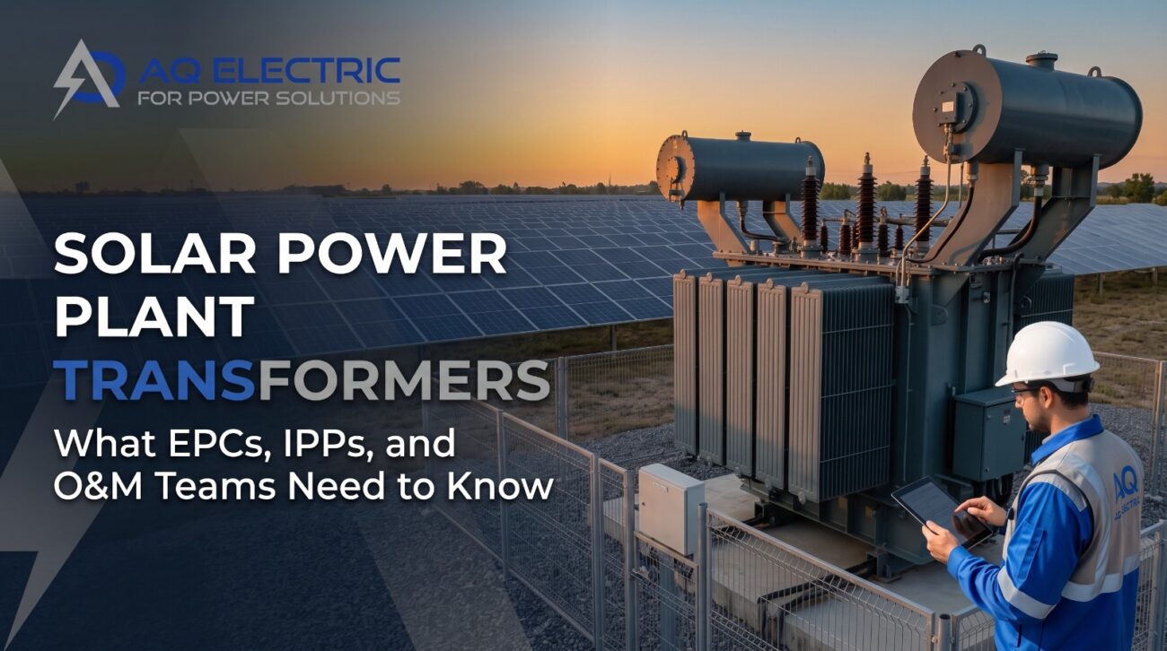
A well-managed transformer O&M programme catches early-warning signs of failure years before they become outages. Six diagnostic activities form the backbone of any credible programme:
Dissolved Gas Analysis (DGA)
Oil sampling and gas analysis is the single most powerful diagnostic tool for oil-immersed transformers. Concentrations of hydrogen, methane, ethane, ethylene, acetylene, carbon monoxide, and carbon dioxide reveal the specific fault mechanism at work — partial discharge, overheating, arcing, or cellulose degradation — often months before visible symptoms appear. Baseline sampling at commissioning followed by annual sampling is the industry standard, with more frequent sampling triggered by any adverse trend.
Infrared Thermographic Scanning
Under load, thermographic imaging of transformer bushings, cable terminations, cooling radiators, and enclosure surfaces reveals hot spots caused by loose connections, cooling failures, or internal winding issues. Six-monthly scanning is a common cadence for utility-scale plants.
Insulation Resistance and Polarisation Index
Annual insulation resistance testing (with polarisation index calculated over 10 minutes) tracks the aging of winding insulation and detects moisture ingress before it becomes a dielectric failure.
Bushing Tan-Delta and Capacitance
HV bushings are one of the most common transformer failure points. Tan-delta and capacitance measurement every 3-5 years detects bushing insulation degradation early enough for planned replacement.
Oil Quality Testing
Beyond DGA, periodic testing of oil dielectric strength, water content, acidity, interfacial tension, and colour tracks the ageing of the oil itself and indicates when oil regeneration or replacement is due.
Tap Changer Maintenance
OLTCs are the most mechanically active part of a transformer and have their own maintenance regime — typically every 3-5 years or after a specified number of tap operations. Contact wear, oil-compartment condition, and drive mechanism function are all checked.
See our solar O&M guide for how transformer testing fits into the plant-wide maintenance programme.
Common Transformer Failure Modes in Solar Plants
From more than a decade of solar plant O&M and third-party inspection work across MENA, the transformer failures that consistently take plants offline fall into six patterns.
1. Bushing Failure
HV bushing insulation degrades over time due to moisture ingress through gaskets, oil contamination, or external contamination on the porcelain surface. A bushing failure typically results in an internal flashover that damages the transformer catastrophically and can propagate to a fire.
2. Cooling System Failure
Radiator fan motor failures, blocked oil circulation, or degraded pumps reduce the transformer’s cooling capacity. In a MENA summer, a partially degraded cooling system doesn’t just reduce headroom — it causes over-temperature trips at plant peak generation, exactly when the plant is most valuable.
3. Winding Insulation Breakdown
Long-term thermal aging combined with dielectric stress eventually breaks down the paper-oil insulation between windings. DGA trend analysis catches this early. Without DGA, the first sign is often a Buchholz alarm minutes before an outage.
4. Moisture Ingress
Failed silica gel breathers, degraded gaskets, or damaged conservator diaphragms allow moisture into the oil. Moisture in oil dramatically reduces dielectric strength and accelerates paper insulation degradation. Water content should be tracked at every oil sample.
5. Tap Changer Contact Failure
OLTC contacts wear, arc, and eventually fail. Symptoms include high contact resistance, unusual DGA patterns from the tap changer compartment, and mechanical position feedback errors. Preventive tap changer overhaul on schedule is far cheaper than emergency intervention.
6. External Short-Circuit Damage
Faults on the MV or HV network external to the transformer can cause mechanical damage to windings even when the transformer’s own protection operates correctly. Post-fault DGA and impedance measurement are essential to confirm the transformer remains fit for service.
MENA-Specific Transformer Challenges
Operating solar power plant transformers in the MENA region introduces stresses that generic global O&M playbooks do not fully address.
Extreme Ambient Temperatures
Summer ambient of 45+ °C at plant sites in Saudi Arabia, the UAE, Egypt’s Western Desert, and Jordan’s Ma’an region reduces the transformer’s available thermal headroom significantly. Cooling systems must be sized for these ambients from the start — retrofitting later is expensive.
Dust and Radiator Fouling
Airborne dust settles on radiator fins and gradually reduces heat rejection. A cleaning schedule for transformer radiators is often missing from generic O&M contracts, but in the MENA context it should be quarterly at minimum.
Coastal Corrosion
At Aqaba, the Red Sea coast, and the Arabian Gulf coastline, salt air aggressively corrodes external transformer components — radiator fins, control cabinets, and bushing supports. Marine-grade coatings and stainless-steel fasteners should be specified from day one for coastal sites.
Remote Sites and Spares Logistics
Utility-scale plants in Ma’an, Aswan, or the Saudi interior can be many hours from urban centres. Local spare parts availability — particularly for bushings, tap changer parts, and cooling system components — is often the difference between a two-day outage and a two-week outage.
Related AQ Electric Services
Explore our full portfolio — each service on its own page.
⚡Testing & Commissioning🔧Operation & Maintenance🔍Third-Party Inspection✓Quality Assurance (FAT & SAT)📐Engineering Services🚁Drone Inspection🎓Training Services✉Speak to an Engineer
solar power plant transformers Testing or O&M?
AQ Electric’s engineering team delivers FAT witnessing, SAT execution, commissioning testing, DGA sampling, thermographic scanning, and periodic maintenance across Jordan, Egypt, Saudi Arabia, the UAE, Oman, Kuwait, and Qatar.
Frequently Asked Questions
What’s the difference between an inverter transformer and a main transformer in a solar plant?
The inverter transformer steps up LV inverter output to the plant’s MV collection voltage. The main (step-up) transformer takes that MV up to the transmission voltage for grid connection. A utility-scale plant has many inverter transformers and typically one main transformer.
What is an auxiliary transformer in a solar power plant used for?
The auxiliary transformer provides internal station-service power for SCADA, control systems, cooling equipment, protection systems, lighting, security, and HVAC. It is small (25–500 kVA) but safety-critical — its failure can take an otherwise-healthy plant fully offline.
How often should transformer DGA sampling be performed?
Baseline at commissioning; annual routine sampling on every oil-immersed transformer; more frequent (quarterly or after events) if any parameter trends adversely. Costs are modest compared to the value of the diagnostic information.
What are the most common causes of transformer failure in MENA solar plants?
In our field experience: cooling system degradation from dust, bushing contamination and moisture ingress, and OLTC contact wear. All three are catchable early with proper thermographic and DGA programmes.
Do solar plant transformers need special design considerations vs traditional applications?
Yes — cyclic loading, inverter-generated harmonics, higher ambient temperatures, and 25+ year design life all require specific attention. K-factor rating, temperature-rise derating, and ester-oil selection are common solar-specific choices.
Can AQ Electric provide transformer testing across the MENA region?
Yes — from FAT witnessing at manufacturers’ works to SAT, commissioning, and periodic O&M testing at sites in Jordan, Egypt, Saudi Arabia, the UAE, Oman, Kuwait, and Qatar. See our testing and commissioning services.
Protecting the Most Expensive Equipment on Your Solar Site
Solar power plant transformers demand specialist testing, commissioning, and O&M expertise. AQ Electric delivers all three with ISO-certified processes and over 1.0 GW of PV project experience across the MENA region.
PV projects supported
MENA countries covered
ISO certifications9001 · 14001 · 45001
Founded in Jordan