Over time, several issues can cause the deterioration of the conductors’ insulation. PV installations commonly have conductors associated with the PV modules. But exposed conductors are subject to damage from wildlife, chafing on racking systems, movement from tracking arrays, and build-up of dirt. All of these conditions can lead to the reduction of a conductor’s insulation.
The loss of resistance can occur gradually, giving plenty of warning if checked regularly Performing the test periodically, typically annually, allows the operator to plan out any equipment replacements, resulting in a lower overall cost.
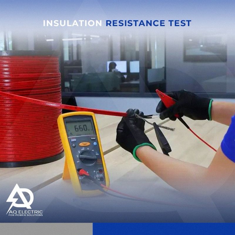
What is an IR Tester?
An insulation tester is a high-range resistance meter (ohmmeter) with a built-in direct current generator. This meter utilizes both current and voltage coils, enabling actual ohms to be read directly, independent of the actual voltage applied.
The battery-powered tool injects a dc voltage on the conductor under test. A complete circuit occurs if a compromised conductor touches anything bonded to earth, like a racking system.
The IR tester uses Ohm’s law to calculate the insulation resistance from the known voltage and current. The digital display tells the technician the insulation resistance for that conductor.
An IR test will place a voltage and a small current on the conductors under test. The tool then uses Ohm’s law to calculate the resistance. A good insulator will have substantial resistance, often not less than 1M Ohm per 1KV according to some IEC standards and industry best practices.
Insulation resistance testing should be part of standard best practices for all PV systems’ quality and safety control checks. Many solar installations require detailed testing and verifications per the IEC 62446 international standard. Benefits include:
– Ensure proper conductor installation before energizing system
– Establish a baseline for future test results
– Verification before installation to catch manufacturing defects
Performing IR tests within a PV array is similar to other electrical circuits, but there are key differences. Proper planning and understanding the required methods will ensure the tests are performed safely and correctly.
1-Document Environmental Conditions
2-Shutdown & LOTO
3-Isolate All Power Electronics
4-PV Circuit Tests: Connect the IR Tester Leads
5-Set the IR Tester to the Desired Voltage Test Level
6-Test the Connected Circuit
7-Record Results
8-Evaluate Results in the Field
Insulation resistance should be approximately one megohm for each 1,000 V of operating voltage, with a minimum of one megohm.
For more information and requests you can reach us,,
– Email: Aqatawneh@aqelectric.net
– Mobile: +201151006630
+962795154126